
Data Centres
Thermal imaging can identify developing switch fuse, isolator and contact defects within electrical systems serving data centres.
Discover MoreSwitch fuses and isolators provide circuit protection, switching and safe means of isolation across low-voltage and high-voltage electrical systems. Thermal imaging can identify abnormal heating at terminals, internal contacts, fuse assemblies, pivots and operating interfaces while equipment remains energised.
Developing defects may result from loose or high-resistance connections, contact wear, loss of contact pressure, corrosion, contamination, mechanical deterioration, repeated operation or age-related degradation. The external appearance may remain unchanged while the current path deteriorates.
Our electrical thermal imaging surveys assess accessible switch fuses and isolators under representative operating conditions. This page explains how connection and contact defects may present thermally across LV equipment and HV line isolators, and why interpretation requires knowledge of load and equipment design.
The consequences depend on the device and circuit. A defect in a local switch fuse may affect one distribution circuit, while poor contact on a 33kV or 132kV isolator may threaten critical substation infrastructure and require a carefully planned response.
Effective assessment considers current, phase comparison, device construction, contact geometry, operating history, environment and the consequences of failure. A thermal pattern can identify abnormal behaviour, but safe physical inspection may be required to establish the precise cause.
For a wider overview, visit our Common Electrical Faults Identified by Thermal Imaging guide. Related contact mechanisms are covered in our High-Resistance Connections guide.
Switch fuse and isolator defects include deteriorated terminals, internal contacts, fuse-holder interfaces, pivots and other current-carrying joints. The device may continue operating while resistance and temperature increase.
At LV, the anomaly may be concentrated around a cable termination or fuse connection. At HV, abnormal heating can occur at exposed switch contacts, pivots and mechanical assemblies that form part of the current path.
Thermography identifies comparative behaviour under load. Follow-up inspection after safe isolation may be needed to distinguish a loose terminal, poor contact, corrosion, mechanical wear or another internal condition.
Deterioration at terminals, switch contacts or fuse interfaces reduces the effective conductive area and creates additional heating under load.
Repeated operation, misalignment, worn pivots and loss of contact pressure can alter the current path and increase electrical resistance.
Outdoor isolators and switchgear can be affected by corrosion, contamination and weathering. These conditions can change surface contact and thermal behaviour over time.
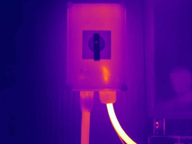
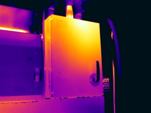
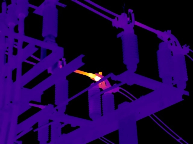
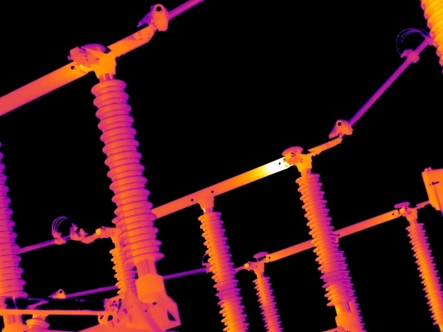
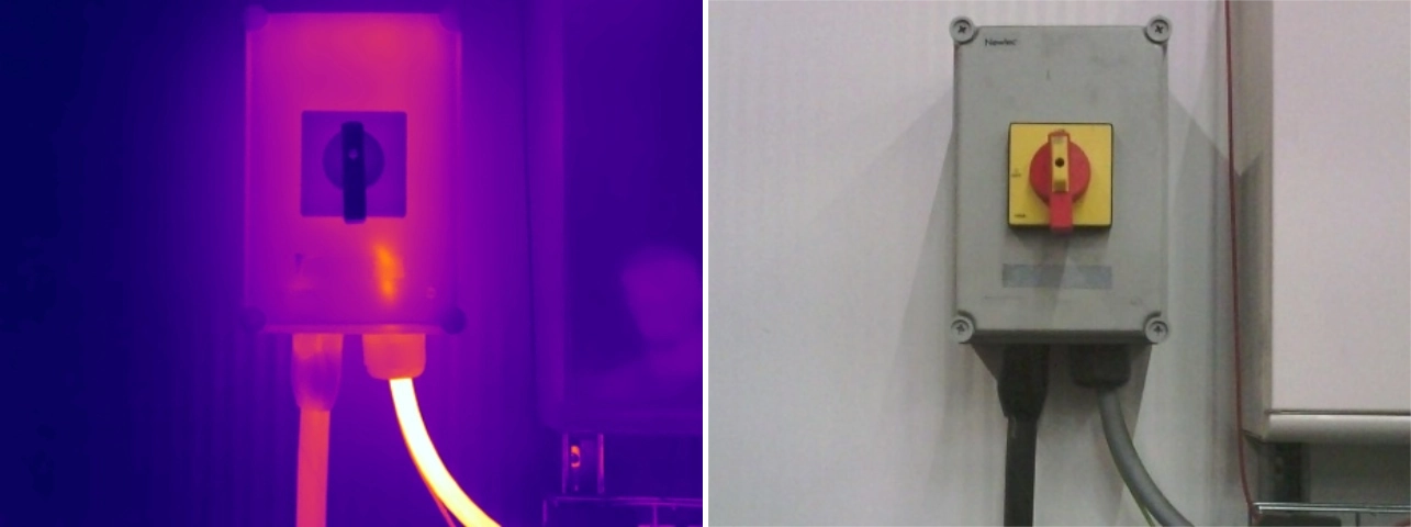
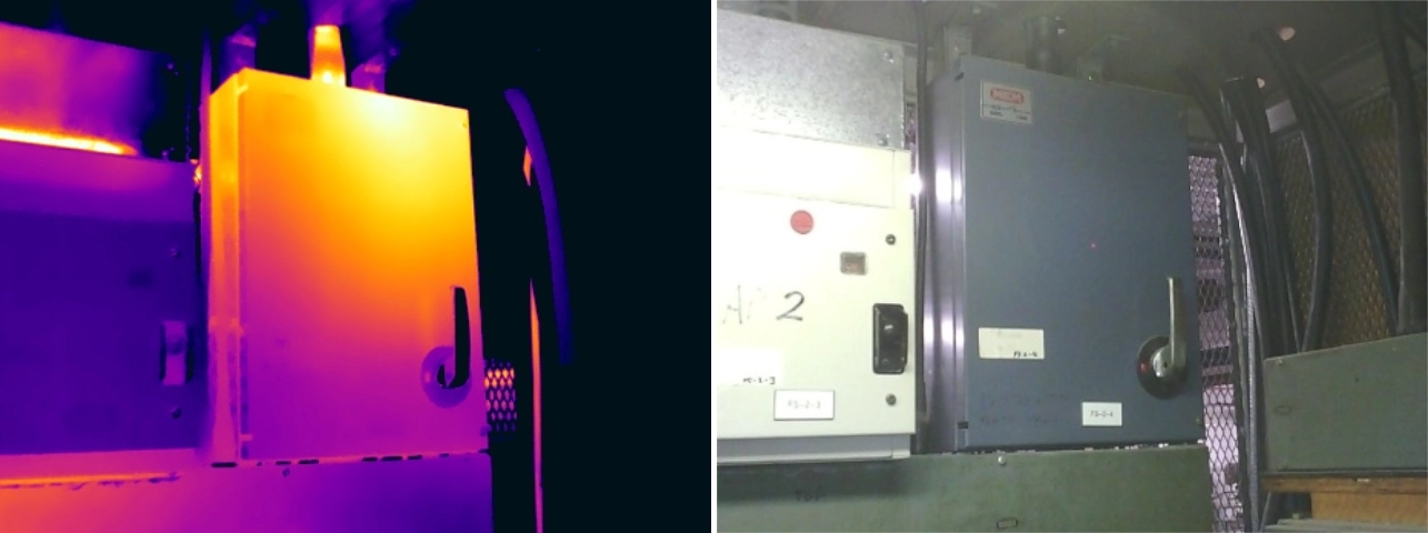
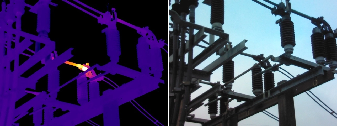
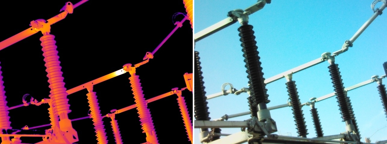
Switching and isolation defects can occur across very different voltage levels. The two examples below add a 33kV actuator-pivot anomaly and 132kV line-isolator contact defect to the LV isolator and switch-fuse examples shown above.
Red Current can assess accessible LV and HV switching equipment under representative load, provide clear thermal and visual evidence, and deliver an independently reviewed report with prioritised recommendations.
Thermal anomalies may occur at switch-fuse cable terminations, fuse carriers, internal contacts, LV isolators, switch disconnectors, main switches, substation isolator pivots and high-voltage line-isolator contacts.
The visible pattern depends on the current path and construction. Terminal heating may be highly localised, while deteriorating internal or exposed contacts can transfer heat through a larger assembly.
The four examples on this page span LV switch fuses and isolators together with 33kV and 132kV equipment. Together they demonstrate the same need for comparative assessment across very different switching arrangements.
Thermal imaging identifies switch fuses and isolators that warrant investigation; it does not replace safe isolation, inspection, testing or maintenance by appropriately competent personnel. Corrective action may include checking terminals, inspecting contacts and pivots, cleaning contaminated interfaces, replacing degraded components or planning specialist HV maintenance.
Where practicable, a follow-up thermal inspection under comparable load can help verify that remedial work has resolved the abnormal pattern. HV work should follow site safety rules, switching procedures and manufacturer requirements.
Red Current can provide a specialist electrical thermal imaging survey or follow-up verification inspection under representative operating load. Our electrically qualified, ITC/PCN certified thermographers provide clear thermal and visual evidence, independently reviewed reporting and prioritised recommendations, while your electrical contractor or HV service provider remains responsible for isolation and remedial work.
A hotspot at a cable termination may indicate a connection defect, while a broader device pattern can originate from internal switch contacts or fuse interfaces.
Pivots, blades and contact assemblies form part of the high-voltage current path. Their thermal pattern must be interpreted with knowledge of the isolator design and comparable phases.
Sun, wind, reflections, contamination and ambient conditions can influence exposed HV equipment. Inspection technique and comparative evidence are essential.
The value of switch fuse and isolator thermography lies in converting thermal evidence and equipment context into a defensible maintenance decision. Red Current’s assessments draw on electrical expertise, ITC/PCN certification, structured review and an in-house knowledge base developed from years of reporting data and millions of thermal images.
Red Current can provide specialist thermal inspection, analysis and reporting while the electrical contractor or HV service company retains responsibility for switching, testing and remedial work.
Realising the full value of an electrical thermal imaging survey depends on the competence of the thermographer, the quality of the inspection process and the clarity of the final report. Red Current combines electrical knowledge, certified thermography expertise and structured quality assurance to provide findings that can be understood, prioritised and acted upon.
Our electrical thermal imaging surveys are undertaken by electrically qualified, ITC/PCN certified thermographers. These recognised certification schemes provide structured training and assessment in infrared thermography, while our electrical qualifications and field experience support safe, technically informed inspection of live electrical systems. Thermographer competence matters because image capture, measurement, interpretation and reporting must be considered together.
Read more about why ITC/PCN thermography certification and surveyor competence matter.
Our survey and reporting processes are aligned with ISO 18434-1, supporting a consistent approach to inspection, analysis and communication of findings. Reports are prepared to give maintenance teams clear evidence, appropriate context and practical priorities.
See our guidance on electrical thermal imaging standards, reporting and survey requirements.
Thermal images alone do not provide a maintenance strategy. Our reporting process turns observations into documented findings with supporting thermal evidence, priority classifications and recommendations that can be used by facilities teams, insurers and electrical contractors.
Find out whether an electrical thermal imaging report can support insurance requirements.
Switching and isolation equipment ranges from LV switch fuses and disconnectors to exposed 33kV and 132kV line isolators. Red Current delivers electrical thermography across commercial, industrial and high-voltage environments, helping ensure each anomaly is assessed in the correct load, equipment and environmental context.
Explore our common electrical faults guide and high-voltage thermal imaging surveys.
Switch fuse and isolator defects can affect every sector that depends on reliable switching, protection and isolation of electrical supplies.
Thermal imaging can identify developing switch fuse, isolator and contact defects within electrical systems serving data centres.
Discover More
Thermal imaging can identify developing switch fuse, isolator and contact defects within electrical systems serving manufacturing facilities.
Discover More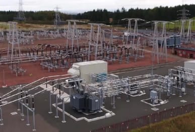
Thermal imaging can identify developing switch fuse, isolator and contact defects within electrical systems serving high voltage substations.
Discover More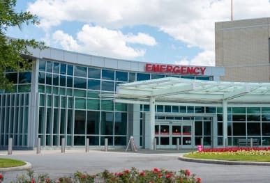
Thermal imaging can identify developing switch fuse, isolator and contact defects within electrical systems serving hospitals & healthcare facilities.
Discover More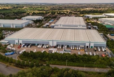
Thermal imaging can identify developing switch fuse, isolator and contact defects within electrical systems serving distribution centres.
Discover More
Thermal imaging can identify developing switch fuse, isolator and contact defects within electrical systems serving food manufacturing facilities.
Discover More
Thermal imaging can identify developing switch fuse, isolator and contact defects within electrical systems serving commercial offices.
Discover More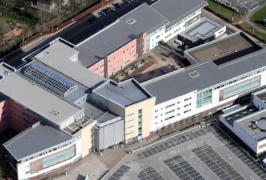
Thermal imaging can identify developing switch fuse, isolator and contact defects within electrical systems serving schools, colleges & universities.
Discover More
Thermal imaging can identify developing switch fuse, isolator and contact defects within electrical systems serving shopping centres & retail parks.
Discover MoreCommon causes include loose or high-resistance terminals, internal contact wear, loss of contact pressure, fuse-holder deterioration, mechanical wear, misalignment, corrosion, contamination and repeated operation.
Yes. Increased resistance commonly creates localised heating under load. Comparison with other poles, phases or similar equipment helps establish significance.
Yes. A terminal or contact defect can generate heat while the fuse remains intact. The cause requires appropriate investigation following safe isolation.
Yes. Pivots and mechanical contact assemblies can form part of the current path. Wear, corrosion or declining contact pressure can create abnormal heating.
Comparative heating at switch contacts can indicate poor electrical contact, but load, phase comparison, environmental conditions and isolator design must be considered.
No. Thermography directs attention to abnormal in-service behaviour but does not replace inspection, testing, lubrication, adjustment or manufacturer-specified maintenance.
Priority considers thermal behaviour, loading, voltage level, equipment type, failure consequences, asset criticality and the risk associated with continued operation.
Specialist thermographers interpret terminals, contacts, pivots and exposed HV equipment alongside load, design and environmental conditions, then provide consistent reporting and actionable recommendations.
For broader survey questions, visit our Electrical Thermal Imaging Survey FAQs.
Thermal imaging can identify abnormal behaviour within switch fuses and isolators while equipment remains in service, but temperature alone does not establish the exact cause. Representative loading, comparative analysis, equipment knowledge and appropriate follow-up investigation are essential if findings are to support sound maintenance decisions.
Red Current provides specialist electrical thermography for end users, facilities teams, insurers and electrical testing companies throughout the UK. Contact us to request pricing, obtain a sample report or discuss a subcontract survey requirement.
Please complete the form below to let us know your requirements. We’ll then provide detailed information on costs and our inspection process.
Please complete the form below to let us know your requirements. We’ll then provide detailed information on costs and our inspection process.
Please complete the form below to let us know your requirements. We’ll then provide detailed information on costs and our inspection process.
Please complete the form below to let us know your requirements. We’ll then provide detailed information on costs and our inspection process.
Please complete the form below to let us know your requirements. We’ll then provide detailed information on costs and our inspection process.
Please complete the form below to let us know your requirements. We’ll then provide detailed information on costs and our inspection process.
Please complete the form below to let us know your requirements. We’ll then provide detailed information on costs and our inspection process.
Please complete the form below to let us know your requirements. We’ll then provide detailed information on costs and our inspection process.
Please complete the form below to let us know your requirements. We’ll then provide detailed information on costs and our inspection process.
Please complete the form below to discover our latest offers on the camera you're interested in.
Please fill out this form for us to generate an invoice. Call us on 0118 3320819 or email your enquiry to our team who are on hand to assist.
Please complete the form below to discover our latest offers on the camera you're interested in.
Please complete the form below to let us know your requirements. We’ll provide detailed information on pricing, availability, delivery options, and our thermal camera hire process.
Once submitted, a member of our team will get in touch with tailored guidance to support your needs.
 ELECTRICAL APPLICATIONSData Centre Thermal InspectionsHigh Voltage Substation SurveysManufacturing Facility InspectionsHospital Thermal InspectionsFood Manufacturing InspectionsDistribution Centre InspectionsOffice Building InspectionsSchool & University InspectionsShopping Centre InspectionsOffshore Oil and Gas Surveys
 OTHER APPLICATIONSUnder Floor Heating InspectionsBuilding Heatloss Surveys


