Data Centres
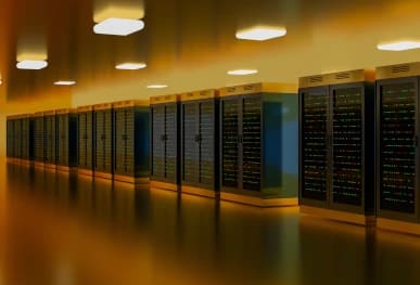
Loose electrical connections can threaten critical power continuity and redundant distribution systems within data centres.
Discover MoreLoose electrical connections are among the most frequently identified defects during electrical thermal imaging surveys. They can develop at cable terminations, bolted joints, busbar connections and component terminals throughout low-voltage and high-voltage systems.
These defects often remain hidden during routine visual checks. Vibration, thermal cycling, mechanical stress, installation quality and equipment ageing can gradually reduce connection integrity until abnormal heating, insulation damage or failure occurs.
Electrical thermal imaging surveys provide a non-invasive way to assess connection behaviour while systems remain energised and operating under representative load. This page explains what loose connections look like thermally, why correct interpretation requires specialist judgement, and how Red Current supports end users and electrical testing companies with qualified surveys and independently reviewed reporting.
The practical consequences vary considerably according to the affected asset. A loose connection within a lightly loaded final circuit may initially present as a developing maintenance issue, whereas a similar defect on a main switchboard, transformer bushing or critical power system may represent a much greater threat to continuity, equipment condition and safety.
Effective thermographic assessment therefore considers far more than the presence of heat. The thermographer must evaluate the location and shape of the anomaly, the electrical load, comparable phases or components, the design of the equipment and the potential consequences of failure. This wider context helps distinguish a genuine connection defect from normal load-related heating and supports a proportionate maintenance response.
For a wider overview, visit our Common Electrical Faults Identified by Thermal Imaging guide.
An electrical connection relies on secure, stable contact between conductive surfaces. When clamping pressure or contact quality is reduced, the effective conductive area can decrease and contact resistance can rise. The connection may continue to operate, but its thermal behaviour can change well before there is visible damage or complete failure.
Loose connections are not limited to one type of installation. They may be found within final distribution equipment, motor control systems, main switchboards, busbar assemblies, transformers, UPS systems and high-voltage assets. The operational significance depends on the affected component, the current being carried, the consequence of failure and the conditions present at the time of inspection.
The term ‘loose connection’ can describe several related conditions, including reduced clamping pressure, a poorly secured conductor, movement within a mechanical joint or loss of effective contact across mating surfaces. The external appearance may remain unchanged, so the significance of the condition is normally established through the thermal pattern, operating context and subsequent inspection following safe isolation.
Under normal conditions, a sound connection allows current to pass with relatively low resistance. If the contact area deteriorates, more energy may be dissipated as heat at the joint. Thermography can reveal the resulting localised pattern while the circuit remains in service.
Heating may accelerate oxidation and material degradation, which can further increase resistance. This feedback mechanism means a connection that initially presents as a modest anomaly can deteriorate as operating conditions continue.
The progression is not always visible externally and is not reliably judged by temperature alone. Changes in electrical load, cooling, contact pressure or the surrounding assembly can alter the thermal pattern. This is why repeatable inspection conditions, electrical context and experienced interpretation are essential.
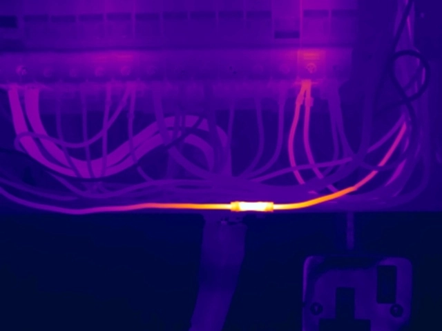
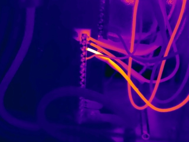
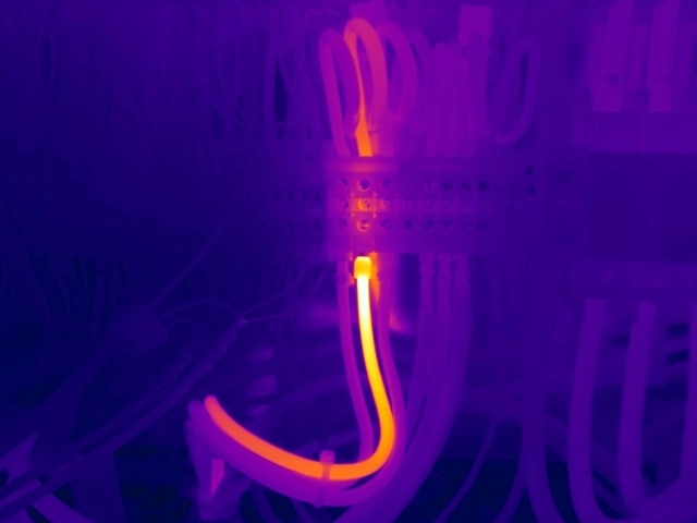
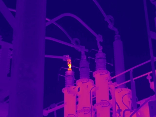
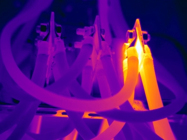
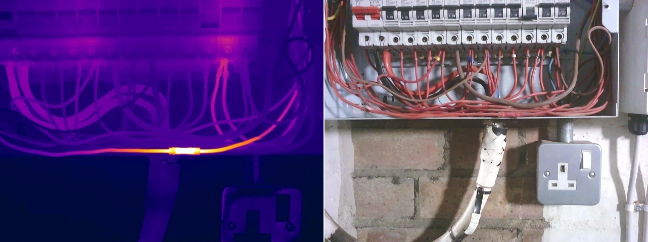
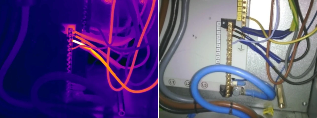
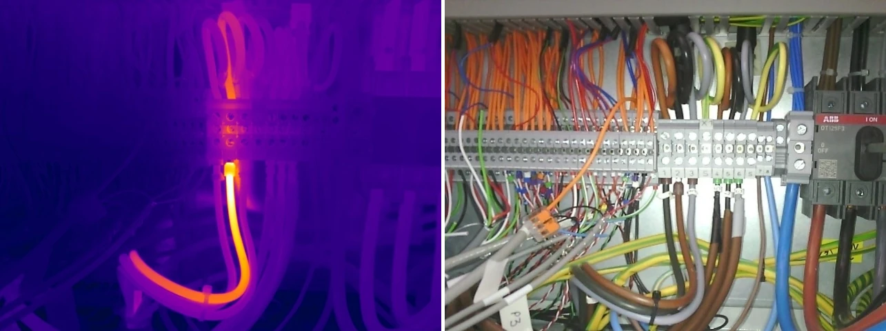
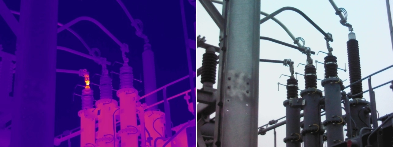
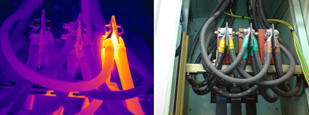
Loose connections can present differently according to the component, current path, loading and stage of deterioration. The examples below retain the thermal image as the principal view; selecting an image opens the matching visual and thermal comparison.
Red Current can assess live electrical equipment under representative load, provide clear thermal and visual evidence, and deliver an independently reviewed report with prioritised recommendations. We also support electrical testing companies that require a specialist thermography partner.
Connection defects can occur wherever conductors, busbars or components rely on mechanical contact. Common examples include distribution boards, switch fuses, isolators, contactors, motor control centres, main switchboards, busbar systems, transformer terminations, UPS distribution and high-voltage substations.
The same underlying mechanism does not always produce the same thermogram. For example, a terminal defect may appear as a highly localised hotspot, while heat from an internal contact can spread across a breaker or switch body. Correct interpretation therefore requires knowledge of the asset and of the current path through it.
The five examples on this page deliberately span a consumer unit, three-phase distribution board, DIN terminal, transformer bushing and LV switchgear busbar assembly. Together they demonstrate that loose connections can occur across very different voltage levels and equipment types without repeating the same image elsewhere on the page.
Thermal imaging identifies where abnormal behaviour warrants attention; it does not replace safe isolation, inspection and remedial work by an appropriately competent electrical contractor. Depending on the defect, corrective work may include inspection of the joint, replacement of damaged components, correction of mechanical strain, treatment of contamination or reinstatement in accordance with the equipment manufacturer's requirements.
Where practicable, a follow-up thermal inspection under suitable operating load can help verify improvement and confirm that the repaired connection is no longer exhibiting the previous abnormal pattern. If comparable loading is unavailable, the finding may need to remain under monitoring until meaningful verification is possible.
Red Current can provide a specialist electrical thermal imaging survey or follow-up verification inspection under suitable operating load. Our electrically qualified, ITC/PCN certified thermographers provide clear thermal and visual evidence, independently reviewed reporting and prioritised recommendations, while your appointed electrical contractor or in-house team remains responsible for safe isolation and any remedial work.
A healthy component carrying greater current than adjacent equipment may naturally operate at a higher temperature. Without representative load data and suitable comparisons, normal behaviour can be incorrectly reported as a defect.
A developing connection problem may show only a modest temperature difference at the time of inspection, particularly where the circuit is lightly loaded. Asset criticality and potential failure consequences may still justify investigation or monitoring.
Thermal mass, component geometry, ventilation, enclosure design, reflections and nearby heat sources can all influence the apparent pattern. The thermographer must distinguish a genuine connection anomaly from load-related or environmentally influenced heating.
The value of an electrical thermal imaging survey lies in turning thermal evidence into a defensible maintenance decision. Red Current's assessments draw on electrical expertise, thermography certification, structured review and an in-house knowledge base of component operating temperatures developed from years of reporting data and millions of thermal images.
This accumulated experience supports consistent prioritisation without disclosing or reducing the work to a simplistic set of temperature rules. It is also why many electrical testing companies choose to subcontract specialist thermography rather than treating the work as an add-on camera exercise.
Electrical testing companies are frequently asked to include thermal imaging alongside fixed-wire testing, condition reporting or planned maintenance activities. Owning a thermal camera may make image capture possible, but delivering a reliable survey also requires appropriate load conditions, thermographic competence, electrical knowledge, image interpretation, fault prioritisation and clear reporting.
Red Current works as a specialist delivery partner where electrical contractors want to retain the client relationship while subcontracting the thermographic element to an experienced provider. Our role can include survey planning, on-site inspection, thermal analysis, priority classification and professional reporting, giving your team a clear specialist output to incorporate into the wider maintenance programme.
This approach reduces the risk of missed or misclassified anomalies, avoids the need to build an internal thermography function for occasional demand, and allows the electrical testing contractor to offer a broader service without presenting thermography as a simple exercise in finding hot spots.
Realising the full value of an electrical thermal imaging survey depends on the competence of the thermographer, the quality of the inspection process and the clarity of the final report. Red Current combines electrical knowledge, certified thermography expertise and structured quality assurance to provide findings that can be understood, prioritised and acted upon.
Our electrical thermal imaging surveys are undertaken by electrically qualified, ITC/PCN certified thermographers. These recognised certification schemes provide structured training and assessment in infrared thermography, while our electrical qualifications and field experience support safe, technically informed inspection of live electrical systems. Thermographer competence matters because image capture, measurement, interpretation and reporting must be considered together.
Read more about why ITC/PCN thermography certification and surveyor competence matter.
Our survey and reporting processes are aligned with ISO 18434-1, supporting a consistent approach to inspection, analysis and communication of findings. Reports are prepared to give maintenance teams clear evidence, appropriate context and practical priorities.
See our guidance on electrical thermal imaging standards, reporting and survey requirements.
Thermal images alone do not provide a maintenance strategy. Our reporting process turns observations into documented findings with supporting thermal evidence, priority classifications and recommendations that can be used by facilities teams, insurers and electrical contractors.
Find out whether an electrical thermal imaging report can support insurance requirements.
Loose connections can occur on compact control terminals, distribution equipment, high-current busbars and transformer bushings. Red Current delivers electrical thermography across commercial, industrial and high-voltage environments, helping ensure each anomaly is considered in the correct asset and operational context.
Explore our common electrical faults guide and high-voltage thermal imaging surveys.
Loose connections can develop across almost every electrical environment. Their operational impact is particularly significant where continuity, life safety, production or critical power systems depend on reliable distribution infrastructure.
Loose electrical connections can threaten critical power continuity and redundant distribution systems within data centres.
Discover More
Vibration, thermal cycling and production demands can contribute to connection deterioration within manufacturing facilities.
Discover More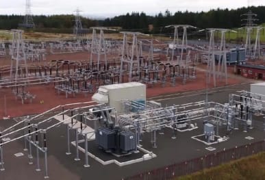
Thermography can identify abnormal connection behaviour across bushings, joints and high-voltage substation equipment.
Discover More
Early detection supports reliable electrical services where continuity is important to healthcare operations.
Discover More
Large distribution facilities depend on reliable switchboards, conveyors, controls and building-services infrastructure.
Discover More
Thermographic inspection helps support continuous production and planned maintenance in food processing environments.
Discover More
Loose connections can affect main distribution, landlord supplies and critical building services within commercial offices.
Discover More
Thermal surveys help estates teams identify developing connection issues and plan work around education activities.
Discover More
Early fault detection supports reliable trading, tenant supplies and building services across retail facilities.
Discover MoreLoose electrical connections can develop through inadequate installation torque, repeated thermal cycling, vibration, conductor movement, mechanical wear, corrosion, contamination and age-related deterioration. The likely cause must be considered alongside the component design and operating conditions.
Yes. Loose connections commonly produce localised abnormal heating because increased contact resistance causes additional energy to be released as heat. A reliable assessment requires suitable loading and comparison with similar components operating under comparable conditions.
Yes. Continued localised heating can damage insulation, accelerate oxidation and increase the likelihood of arcing or equipment failure. The severity of the risk depends on the asset, loading conditions, surrounding materials and consequences of failure.
No. A genuine connection defect may show only a modest temperature rise, while a healthy component carrying greater load may be relatively hot. Thermographers assess thermal patterns, loading, component design and comparative behaviour rather than relying on absolute temperature alone.
No. Thermal imaging and conventional electrical testing provide different information. Thermography assesses thermal behaviour under load and can reveal issues that may not be apparent during other inspections, but it should complement rather than replace an appropriate electrical maintenance and testing programme.
Yes. A connection may deteriorate gradually before reaching a point where insulation damage, arcing or mechanical failure occurs. Periodic thermographic inspection can help identify developing conditions before that point is reached.
The response is based on more than temperature. Loading, equipment criticality, failure consequences, component type, accessibility, comparative thermal behaviour and operational risk all contribute to the priority classification.
Capturing a thermogram is only one part of a survey. Specialist thermographers interpret loading, thermal patterns, equipment design and failure mechanisms, then communicate findings through consistent reporting and actionable priorities. This is particularly valuable to electrical testing companies that need a reliable specialist partner for thermographic work.
For broader survey questions, visit our Electrical Thermal Imaging Survey FAQs.
Loose electrical connections are among the most frequently encountered electrical defects, but their significance cannot be judged simply by finding the hottest object in an enclosure. Suitable operating conditions, comparative analysis, component knowledge and an understanding of failure consequences are essential if thermal findings are to support sound maintenance decisions.
Red Current provides specialist electrical thermography for end users, facilities teams, insurers and electrical testing companies throughout the UK. Contact us to request pricing, obtain a sample report or discuss a subcontract survey requirement.
Please complete the form below to let us know your requirements. We’ll then provide detailed information on costs and our inspection process.
Please complete the form below to let us know your requirements. We’ll then provide detailed information on costs and our inspection process.
Please complete the form below to let us know your requirements. We’ll then provide detailed information on costs and our inspection process.
Please complete the form below to let us know your requirements. We’ll then provide detailed information on costs and our inspection process.
Please complete the form below to let us know your requirements. We’ll then provide detailed information on costs and our inspection process.
Please complete the form below to let us know your requirements. We’ll then provide detailed information on costs and our inspection process.
Please complete the form below to let us know your requirements. We’ll then provide detailed information on costs and our inspection process.
Please complete the form below to let us know your requirements. We’ll then provide detailed information on costs and our inspection process.
Please complete the form below to let us know your requirements. We’ll then provide detailed information on costs and our inspection process.
Please complete the form below to discover our latest offers on the camera you're interested in.
Please fill out this form for us to generate an invoice. Call us on 0118 3320819 or email your enquiry to our team who are on hand to assist.
Please complete the form below to discover our latest offers on the camera you're interested in.
Please complete the form below to let us know your requirements. We’ll provide detailed information on pricing, availability, delivery options, and our thermal camera hire process.
Once submitted, a member of our team will get in touch with tailored guidance to support your needs.
 ELECTRICAL APPLICATIONSData Centre Thermal InspectionsHigh Voltage Substation SurveysManufacturing Facility InspectionsHospital Thermal InspectionsFood Manufacturing InspectionsDistribution Centre InspectionsOffice Building InspectionsSchool & University InspectionsShopping Centre InspectionsOffshore Oil and Gas Surveys
 OTHER APPLICATIONSUnder Floor Heating InspectionsBuilding Heatloss Surveys


